A four-on-one illustration shows a regular axial slice from a CT scan of the shoulder, a multiplanar reconstruction slice in the oblique coronal plane, a maximum intensity projection of the bones, and a colorized 3D image showing the shoulder with shadowing and the lung as pink. Images courtesy of Mark Herbst, MD. A four-on-one illustration shows a regular axial slice from a CT scan of the shoulder, a multiplanar reconstruction slice in the oblique coronal plane, a maximum intensity projection of the bones, and a colorized 3D image showing the shoulder with shadowing and the lung as pink. Images courtesy of Mark Herbst, MD. |
Not too many years from now, radiologists and surgeons will be riding a new technological wave.
For Mark Herbst, MD, in St Petersburg, Fla, the future is now, and the water feels fine. “The wave of the future is digital,” says Herbst, who, as owner of St Petersburg Independent Diagnostic Radiology (www.spin-dr.com), reads digital images from nearly 40 sites every day.
“Even before you reconstruct images in three dimensions, you can see things so much better in the digital image format,” says Herbst. “By making window level and zoom adjustments, you can find evidence that is essential for surgeons on an image, which, if read on film, might appear normal.”
The leap from two to three dimensions in the digital environment is increasingly accessible, as software to perform the reformatting becomes swifter and more user-friendly and more radiology departments adopt picture archiving and communications systems. Until recently, the software to perform reconstructions, including multiplanar reconstruction (MPR), maximum intensity projection (MIP), or three-dimensional colorized reconstruction (3D), was available only on the modality’s own computer or on an expensive, stand-alone workstation. Now, every radiologist can have his or her own software and reconstruct images as needed on the fly.
With MPR, radiologists can take the volume of imaging information and reslice it, reconstructing it in a different plane. Thus, a computed tomographic scan can become a three-dimensional image.
With MIP, three-dimensional images are generated from computed tomography or magnetic resonance scans. This is helpful in angiography, for example, because images isolating the blood vessels are produced, and these can be rotated in space. Thus, instead of subjecting the patient to an invasive test or procedure, surgeons can possibly gain sufficient evidence from these three-dimensional views of the arteries and veins to enable development of a noninvasive or surgical management plan. This technique also works particularly well for bones on CT scans.
THE VIRTUAL PATIENT
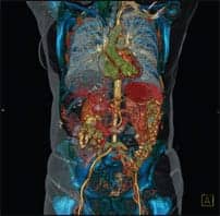
The term “3D imaging” involves making an image look like it is a structure in real space. Layers of anatomical features, including a skeleton, can be incorporated, producing an image that looks like an actual patient. Then specific featuresparticular bones, for example—can be taken away with the click of a button to enable visualization of a feature that has been obscured.
“Surgeons love this,” notes Herbst. “To be able to see inside the patient’s body, and have all the systems and components in bright color and three dimensions is awesome.” And yet, although three-dimensional manipulations are new and attractive (or maybe because of this), he has never had a surgeon call and say, “I need this in 3D.”
“The technology is there, but it is very new, and even most newly trained doctors have not been exposed to it yet,” Herbst explains. And even though he produces the three-dimensional images, “for the most part they will study my report rather than the images, and find the disc herniation or whatever on the films.
“The 3D image is prettya nice extra—but at this stage it is still a novelty. A radiologist can build’ a 3D image in his or her brain and then go through the slices to see the extent of the abnormality. Basically, the 3D images reinforce but are no substitute for the raw data,” he emphasizes.
Christoph Wald, MD, director of Advanced Image Analysis and Virtual Surgical Planning at Lahey Clinic Medical Center (Burlington, Mass), affiliated with Tufts University Medical School, agrees with this, but only partially. “Radiologists are used to putting together 3D anatomic relationships from looking at axial images, but surgeons find that difficult. A single 3D image can often replace dozens of axial images. While there are only some clinical situations in which the diagnosis can be established just with 3D imaging, certainly the illustration of diagnoses is much easier with 3D images.”
HANDY APPLICATIONS
Herbst notes that an added-value feature of the three-dimensional technique is that it can be used to manipulate traditional imaging data as if it were from a three-dimensional dataset. For example, in magnetic resonance imaging of the lumbar spine, sagittal and axial views typically are obtained. What happens if a herniation is seen, say, at T11-12, and no axial images are available? “The radiologist who has 3D software on the reading station can reslice and remanipulate the captured images to create pictures of the transverse plane,” Herbst explains, “and then he or she will be able to describe the herniation more fully.”
Another example of the three-dimensional imaging spectrum is presented in the traditional use of computed tomography of the sinuses. Typically, axial and coronal plane images would be captured; however, dental fillings can cause streaks across the coronal images, making them difficult to read. Now, with three-dimensional manipulation, the coronal plane view can be reconstructed from the axial view, with the metal artifacts eliminated. This is very helpful for the technician, who can obtain the best slice thickness. And because only one view need be obtained, the time involved for both the patient and the technologist is reduced.
This is one of the exciting benefits of three-dimensional imaging, says Wald. “The objective is to be able to obtain all of a patient’s relevant anatomy fast,” he notes. “If you’re able to acquire the target volume from within seconds to anything less than a breath-hold, you can freeze adversarial biologic motion: respiration, cardiac motion, bowel motion.”
More important, Wald notes, is that “if you coordinate image acquisition with high-speed automatic contrast injection, you can record the same volume of interest several times over, thereby documenting the enhancement of normal or abnormal structures during different phases of the contrast passage—arterial, venous, delayed. This greatly enhances the ability to make specific diagnoses or, for instance, depict blood vessels.”
PREREQUISITE TOOLS
Wald explains that state-of-the-art three-dimensional imaging requires two main components: (1) current cross-sectional scanner technology (specifically, ultrafast multidetector-row helical computed tomography scanners and contemporary high-field-strength MRI scanners with fast gradients; to a lesser degree, ultrasound is used) and (2) appropriate workstations and three-dimensional rendering software.
“Only these modern scanners are able to produce the sufficiently high-resolution datasets needed for optimal results during postprocessing on workstations,” he says. “It’s hard to make a bad dataset look good, no matter how fancy the software used.”
Sufficient pretest clinical information is essential, Wald explains. “The scanning protocols are quite individualized to the clinical question as well as the individual patient. Renal function, cardiac output, size of the patient-these and other factors influence the specific protocol.”
Having modern, fast workstations, ideally networked to the scanner or image archiving system through a broad-bandwidth connection, is the second essential component of three-dimensional imaging, Wald notes. “Sometimes thousands of raw images travel over the network and then need to be processed, so speed is of the essence to achieve effective work flow.”
Herbst agrees, adding, “Digital transmission enables radiologists to receive images at almost the speed of light. Using couriers to transport conventional films will soon become obsolete.”
With three-dimensional imaging, modern rendering software is employed to perform the postprocessing phase, Wald explains. “These programs can perform various analyses of the dataset, from 3D renderings to creation of very realistic representations of normal or disease processes; complex mathematical analyses can be performed and the results graphically depicted, as in CT or MR perfusion imaging or spectroscopy. CT or MR angiographic images mimic the images familiar to the surgeon from invasive catheter-based angiography. Three-dimensional and multiplanar views of bones, joints, and associated structures may provide extremely accurate guidance for the surgeon, such as in cases of complex fractures.”
Wald is an enthusiastic advocate of virtual surgical planning. “There simply is no other radiologic surgical planning technique that more accurately simulates the situation in the operating room. This provides a great advantage to surgeons from a planning point of view and also contributes significantly to increasing patients’ safety and decreasing complications.”
It is important that the radiologist be very familiar with the key information the surgeon needs to make operative and treatment planning decisions. To a certain degree, the radiologist needs to be familiar with various options and techniques. “A team approach, with feedback to the radiologist, is key for establishing and improving planning technique,” Wald emphasizes. “Intraoperative findings need to be correlated with preoperative imaging findings.”
PRACTICALITIES, PROTOCOLS
Wald offers some of the practical features that make three-dimensional imaging an attractive technique, not just as a planning tool but also in terms of its impact on patients, doctors, and facilities. “MR angiography [MRA] and CT angiography [CTA] represent noninvasive diagnostic and planning tools that in the appropriate clinical setting successfully replace invasive catheter-based angiography. This is associated with fewer complications for the patient and often saves on costs as well as reducing the time spent in the hospital. Angiography—with preparation, procedure, and postprocedure observation time—can easily exceed 8 hours, often more. In comparison, patients may spend less than 1 hour total in the hospital undergoing CTA.”
The additional information derived from the postprocessing comes at no additional expense of radiation dose or contrast to the patient and is often less expensive and, in the appropriate clinical setting, can be more comprehensive than invasive tests or more conventional cross-sectional or projectional radiographic evaluation. “Unfortunately, this comes at a price,” Wald warns. “A trained individual, most often a radiologist, needs to closely monitor the process and/or perform the workstation analysis, which can be time-consuming. The current reimbursement doesn’t reflect this reality at all. Separate reimbursement for the workhorses’CTA and MRAhas been wiped out by CMS; departments are expected to perform these additional tasks at no extra cost. This represents at best a disincentive for wide use of these extremely beneficial technologies and should be rectified as soon as possible by increasing the reimbursement for CTA and MRA, to a reasonable level that reflects the higher costs associated with the mandatory image postprocessing.”
What will it take for the use of three-dimensional imaging to become mainstream? The field is in the midst of a transition, says Herbst, who sees increasing applications for surgeons. “With the advent of computer-aided neuronavigational surgery, in which the patient undergoes scanning with markers and the 3D reconstructed image is displayed for the surgeon in the operating room, digital technology has already entered the operating arena. ENT surgeons are also taking advantage of this technology for sinus surgery. In the future, many kinds of surgeons will be using 3D data in the operating room to ascertain the best approach and enhance the surgical procedure and outcome.”
First, the cost of digital software and hardware must drop, because “hospitals are not going to be ordering this equipment if it is prohibitively expensive, and the current software programs cost upward of $10,000,” Herbst attests. “Even large radiology departments are just now beginning to plan and order the equipment for digital PAC systems,” which are the foundation of three-dimensional imaging technology, Herbst believes.
Increasing Internet connection speeds will be a plus, but most essential is wider acceptance of the technology among radiologists, says Herbst. Some are simply not comfortable with the concept of reading off of a monitor, which definitely is an impediment to advancement of the technology. However, today’s medical residents are becoming familiar with three-dimensional reconstructions, are learning to operate from them, and are becoming aware of the implications of the technology.
A LOOK AHEAD
What does the future hold for three-dimensional imaging? As this new generation begins practicing in the field, “it will become routine to supply 3D reconstructions along with the original images,” Herbst asserts. “Radiologists will put these into a database, and they will be on a monitor in the operating room. The surgeon will be able to page through the images for reference during the procedure.”
Wald, too, anticipates that great strides will be taken with the new technology. “Accurate preoperative imaging, depicting normal anatomy, aberrant anatomy, and pathologic findings and how exactly they relate to normal structures, in addition to precise vascular maps, all contribute to more complete anticipation of the extent of a surgical procedure,” he asserts.
In addition, Wald says, “Preoperative 3D imaging may help to stratify patients into groups suitable for a minimally invasive approach or requiring open surgery. The ever-increasing number of minimally invasive surgical techniques, especially, can greatly benefit from this technology, as many are associated with limited intraoperative visualization of anatomy.”
Moreover, for live-donor adult liver transplantation, Wald explains, “there is no alternative to 3D planning, no matter whether the datasets are obtained with CT or MRI. Preoperative 3D imaging, including vascular analysis (arterial and venous maps) and volumetric analysis, is key for the selection of appropriate donor candidates. Only 3D imaging on a suitable workstation allows for simulation of the hemihepatectomy and calculation of the resulting graft and remnant volumes.”
But the benefit in transplantation goes beyond the planning aspects, Wald notes. “This technology not only avoids surgery in healthy donors with unsuitable anatomy and enhances intraoperative safety for those deemed suitable, but it also may in the future serve to expand the pool of candidates [for liver transplantation] by means of a more detailed volumetric analysis of partial liver volumes.”
To put it simply, says Herbst, “You can detect abnormalities better on a full digital-image format than a printed format. Even if images are not acquired in the optimal plane, 3D technology allows us to show the surgeons what they need to see. And then, ultimately, the patients benefit.”
3D Imaging of the Renal VasculatureBy Christoph Wald, MD, PhD The author presents a recent surgical case in which three-dimensional imaging of the renal vasculature enhanced preoperative planning and intraoperative control and minimized postoperative complications. CASE REPORTThe patient, a 35-year-old male, had a history of left retroperitoneal sarcoma treated with resection and radiation during childhood. The patient underwent an abdominal imaging study at another institution, which revealed a right renal mass. He was referred to our institution for surgical treatment.
The patient underwent contrast-enhanced multiphasic CT according to our standard surgical planning protocol, including arterial, venous, and delayed-phase imaging on an 8-slice multidetector CT scanner. Images were then transferred to a workstation for analysis. CT revealed a contralateral small left kidney, probably atrophic secondary to remote radiotherapy during childhood that inhibited growth. This finding provided further support for a nephron-sparing surgical approach in this patient with a functionally solitary kidney affected by tumor. Multiplanar images nicely illustrated significant central (renal sinus/hilar) extension of the tumor, arising in the lower pole of the right kidney (Figure 1). In particular, the tumor’s close association with the lower pole collecting system is of note; some infundibula were stretched, and the lower pole calyx was compressed/occluded. The anticipation of a complex resection involving renal sinus structures and possibly partial resection of the collecting system with reconstruction represented important preoperative knowledge for the surgeons. This tumor could not be adequately removed during the warm ischemic time of 30 minutes for the kidney. The surgeons were therefore able to prepare for in situ cooling (extending the ischemic interval to 60 minutes), with potential for “bench surgery” and autotransplantation of the kidney. Volume rendered images nicely demonstrated the renal vasculature, including the renal artery course and venous anatomy, in particular the segmental contributing veins arising from the right lower renal pole (Figure 2). The intraoperative correlation picture illustrated concordance of the findings (Figure 3). Accurate preoperative identification of the renal vasculature helped gain vascular control during surgery, minimizing complications. Christoph Wald, MD, PhD, is director, Advanced Image Analysis and Virtual Surgical Planning Center, the Lahey Clinic, Burlington, Mass.
|
 Figure 1. Sagittal reconstructed thick slab through right kidney (K) demonstrates significant central extension of lower pole tumor (TU) as well as its intimate relationship with the collecting system (C).
  Figure 2. Posterior view shows a single right renal artery (RA) off the aorta (AO).
  Figure 3. Color volume rendered image of the retroperitoneum shows atrophic left kidney. The right kidney is shown during renal venous phase demonstrating main renal vein (RV), two segmental branches draining the lower pole (V1 and V2). Figure 4. Surgical correlation; intraoperative image of the exposed right kidney shows perfect concordance of 3D image findings with operative situs, right renal vein (RV) as well as segmental lower pole branches are marked (V1, V2). Images courtesy of Christoph Wald, MD, PhD.
 Seleen Street Collins, is a contributing writer for Decisions in Axis Imaging News.