|
Silver-halide-based films have been the primary medium for detecting, recording, and displaying x-ray images since the first observation of x-rays by Roentgen. Indeed, this technology has been used so extensively that the variations in x-ray fluence observed in radiographs are conventionally referred to in terms of “densities.” In the last two decades, however, advances in digital imaging have produced an array of new technologies that have many advantages over film. These digital radiography (DR) technologies affect the techniques by which radiographic images are acquired, stored, managed, viewed, and interpreted. The transition to digital radiography has accelerated in the last few years with the emergence of an increasing number of competitive technologies and the economic incentives to move toward filmless radiography departments. This article considers some of these advances including detector technology, acquisition issues, display of images, and data management. In the next article of this series, we will further explore this topic.
Advances in Detector Technology
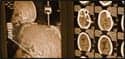
Computed Radiography. Computed radiography (CR) is the most established of the digital radiography technologies available, having seen more than 20 years of clinical use; yet numerous innovations are currently coming to the market. Today, most CR installations closely emulate screen-film radiography using a cassette-based detector. Although a small number of cassetteless CR systems have been used, most have experienced limited success due to mechanical complexity. The situation is changing today as new line-scan systems with advanced phosphor structures are now becoming available. Conventional CR phosphor screens consist of a granular phosphor held in a binder (see Figure 1). Light stimulated in the phosphor is subject to two forms of scattering or blurring: scattering of the stimulating laser light and scattering of the stimulated light emitted by the phosphor particles. Storage phosphors based on needle-like structures allow light to be channeled out of the screen with little lateral spread, making possible screens with greater thickness, thus improving absorption efficiency without decreasing spatial resolution (see Figure 2). A problem, however, is that columnar phosphors are not physically robust, and cannot be used in cassettes like granular phosphor screens. However, when used in combination with the new line-scan readouts with charge-coupled device (CCD) detector arrays, a large variety of fixed installations are possible due to the combination of rapid readout and a compact detector package. Such devices differ little from the DR detectors discussed below.
 Figure 1. Schematic cross section of granular phosphor showing the broad spread of light. Inset is a photograph of such a phosphor. Image courtesy of Ehsan Samei, PhD, Duke University, Durham. Reprinted with permission from: Samei E. Performance of digital radiographic detectors: factors affecting sharpness and noise. In: Samei E, Flynn MJ, eds. Syllabus: Advances in digital radiography-categorical course in diagnostic radiology physics. Oak Brook, Ill: Radiological Society of North America; 2003:49-61. Figure 1. Schematic cross section of granular phosphor showing the broad spread of light. Inset is a photograph of such a phosphor. Image courtesy of Ehsan Samei, PhD, Duke University, Durham. Reprinted with permission from: Samei E. Performance of digital radiographic detectors: factors affecting sharpness and noise. In: Samei E, Flynn MJ, eds. Syllabus: Advances in digital radiography-categorical course in diagnostic radiology physics. Oak Brook, Ill: Radiological Society of North America; 2003:49-61. |
In another innovation, CR manufacturers have introduced a thicker phosphor layered on a light-transparent base. This modification allows dual-side readout by incorporating two light-guide assemblies in the reader, which in turn permits capture of a greater fraction of the light signal, and/or use of a smaller laser beam. Improvements of up to 50% in detective quantum efficiency have been reported. 1
Dual-energy imaging, while not new, is likely to become more prevalent due to innovations in dual-screen detectors. Previous implementations required multiple exposures and/or handling of multiple plates, and careful image registration. New implementations now allow single-exposure, cassetteless dual-energy imaging through the use of automated plate handling, built-in metal filters, and software that speeds image registration enough to allow approximately 40 exposures per hour to be acquired. 2 Clinically, dual-energy imaging has shown significant benefit in the improved detection of lung cancer. 3
Digital Radiography. DR systems initially had an advantage over CR in terms of detector image quality metrics (eg, detective quantum efficiency [DQE]), acquisition speed, and small size. DR systems also have the advantage of a cassetteless design, which results in improved clinical throughput. The advent of advanced cassetteless CR systems such as the line-scan approach, blurs the distinction between CR and DR in terms of acquisition speed and size. Meanwhile, enhanced DR positioning flexibility and detector portability are making inroads into the CR domain.
 Figure 2. Cross sectional of a structured phosphor showing limited lateral spread of light. Image courtesy of Ehsan Samei, PhD, Duke University Medical Center, Durham, NC. Reprinted with permission from: Samei E. Performance of digital radiographic detectors: factors affecting sharpness and noise. In: Samei E, Flynn MJ, eds. Syllabus: Advances in digital radiography-categorical course in diagnostic radiology physics. Oak Brook, Ill: Radiological Society of North America; 2003:49-61. Figure 2. Cross sectional of a structured phosphor showing limited lateral spread of light. Image courtesy of Ehsan Samei, PhD, Duke University Medical Center, Durham, NC. Reprinted with permission from: Samei E. Performance of digital radiographic detectors: factors affecting sharpness and noise. In: Samei E, Flynn MJ, eds. Syllabus: Advances in digital radiography-categorical course in diagnostic radiology physics. Oak Brook, Ill: Radiological Society of North America; 2003:49-61. |
Coupling a flat-panel thin-film transistor (TFT) array with an x-ray absorber can create a highly efficient DR system. Flat-panel DR systems are available using either phosphors (indirect capture) or photoconductors (direct capture). Both DR technologies have been found to be superior to screen-film and current implementations of CR, in terms of quantitative measures such as DQE and in the observed quality of images for clinical purposes. 4 Additionally, the large dynamic range of these systems reduces the need to repeat procedures due to overor underexposure. One disadvantage relative to film and CR is that the detectors are somewhat fragile and can be damaged by rough handling or dropping. For screen-film and CR systems, if a cassette is dropped and damaged, it can be easily replaced. For DR systems, a single DR panel might represent the imaging capacity of an entire radiographic department and can be worth tens of thousands of dollars. Despite this issue, at least one manufacturer has introduced a bedside unit.
While CR systems have a resolution similar to that of screen-film systems and a detection efficiency that can be slightly less, this is not the case for DR systems. DR systems with cesium iodide phosphors have detection efficiencies that are about three times better than those of CR or screen-film systems. DR systems with selenium solid state detectors have an efficiency that is about twice that of CR but exceptionally good resolution with high modulation transfer up to the limiting spatial frequency associated with the detector pixel size.
A number of innovations are likely to occur in DR. As DR is a fairly new technology, improvements in phosphor and photoconductor technology continue apace. Increased readout speed is making dual-energy 3 and tomosynthesis possible. 5 Further in the future it is possible that flexible substrates will replace glass for the TFT array, making DR detectors more robust, which would be highly desirable for bedside use.
Charge-coupled Device. CCD-based systems use lenses or fiber-optics to produce an image with a CCD of an x-ray absorber. Early systems were plagued by low light collection efficiency due to the mismatch between the CCD size and the x-ray absorber size. Recently, however, there have been improvements in scintillators, optical lenses, and CCD cameras that have partially overcome this issue. This said, CCD-based systems in general still lag behind in comparison to TFT-based DR systems with respect to image quality at a comparable dose. The chief advantage of CCD-based systems is price, thus there will continue to be a market segment for CCD-based systems for the foreseeable future.
Image Processing and QC stations
 J. Anthony Seibert, PhD J. Anthony Seibert, PhD |
The development of CR and DR detector technology has occurred in parallel with development of image processing and image quality control (QC). Digitally acquired images must undergo a number of processing steps to produce images that are clinically acceptable. These corrections occur for a variety of reasons, including detector nonuniformities and defects, and the need for edge enhancement, noise reduction, dynamic range compression, and other techniques to improve the visibility of specific diseases and organ systems. These procedures are specific to the detector and the imaging procedure, but can be generalized to some degree.
Detector-specific processing is generally referred to as “preprocessing.” Steps include correction for nonfunctioning detector elements in DR and corrections for scanning artifacts in CR and scanning DR systems. DR systems and CR systems such as the line-scan technology can further undergo a “flat-fielding” operation in which spatial variations in the background signal and gain (so-called fixed pattern noise) are normalized. For cassette-based CR that process many screens, pixel nonuniformities can not be corrected and some fixed pattern noise may remain in the image.
 Andrew Maidment, PhD Andrew Maidment, PhD |
After flat-fielding, additional imaging processing is necessary to match the range of signal intensities in the images to those to be displayed on a film or workstation. As discussed below, the required use of a value of interest look-up table (VOILUT) in the digital x-ray (DX) Digital Imaging and Communications in Medicine (DICOM) object and grayscale standardization has simplified this procedure to some degree, as image rendition is independent of the display modality. For this reason, the use of the DX DICOM object is strongly recommended. Additional processing will depend on the imaging procedure; however, the most relevant is dynamic range compression, as the digital detectors available today can typically produce images with 4,096 graylevels, but typical workstations display only 256 graylevels. For example, dynamic range compression allows the simultaneous display of the lung fields, retrocardiac shadow, and mediastinum in digital chest radiography without compromise of contrast in any of those regions. Additional processing includes detection and removal of the collimator shadow through “electronic collimation,” and in some cases, the removal of the unattenuated portion of the x-ray image, especially if the image is displayed with inverted intensity.
 Michael J. Flynn, PhD Michael J. Flynn, PhD |
Every DR and CR manufacturer today is striving to optimize the display of their images. CR manufacturers have a distinct advantage due to the longer availability of such products. Nevertheless, DR images tend to be technically superior at this time (due, for example, to the ability to remove fixed pattern noise). This is a rapidly changing area of product development.
The increasing complexity of image processing has necessitated the development of image quality control workstations for technologists. In cassette-based CR, these tend to be independent workstations. In DR and cassetteless CR, these functions tend to be integrated into the acquisition system. Such workstation functionality is essential in every CR/DR installation. The workstations provide the technologist with the ability to review the processed image, and to guide the reprocessing of images when necessary. It should also be possible for the technologist to reject images based on image quality and/or positioning, and allow repeat images. Some manufacturers allow statistics to be gathered based on these interventions. These image review QC workstations also introduce the possibility of advanced processing, such as stitching images for long-view procedures (scoliosis and full leg images). Numerous other innovations have also been proposed. For example, higher-resolution detectors, especially in DR, have required the use of higher density grids and/or moving grids. Recently, software corrections have been investigated for grid artifact removal.
Display of CR/DR images
Until recently, monochrome monitors with cathode ray tubes (CRTs) have been used for medical imaging display. For diagnostic interpretations, portrait monitors with 5 million pixels (2500 x 2000) made with fine grain emission phosphors (P45) and precisely focused electron beams have been the recommended device for digital radiographs. In the past year, this has changed dramatically. The quality and price of modern flat panel monitors using liquid crystal display (LCD) panels have improved so rapidly that most centers now find them to be superior. Improved pixel sharpness makes a 3 million pixel (2000 x 1500) LCD equivalent to a 5 million pixel CRT. The brightness and stability of monochrome LCD monitors are excellent and noise is minimal. Some artifacts are introduced at oblique viewing angles, but this has not hindered use for diagnostic interpretation.
Ideally, a monitor used for digital radiographs should be capable of displaying all acquired pixels, which range from 4 to 7 million pixels depending on the acquisition device. The monitor pixel size should match the limits of visual acuity at the expected viewing distance: 0.1 mm at a close distance of 33 cm and 0.2 mm at a normal distance of 66 cm. For a 3000 x 2500 monitor with 0.1 mm pixels, a 7.5 million pixel radiograph can be displayed and viewed at full detail with the eye moved close to the display (33 cm). At a normal viewing distance (66 cm), the image needs to be magnified 2X to appreciate the full detail and panned to see the full area. For a 2000 x 1500 monitor with 0.2 mm pixels, the same radiograph must be minified by about 2/3 to display the full field and should not be viewed by moving the eye to a close distance. However, at a normal viewing distance, the full detail is visible and the full area can be viewed with modest panning. In this manner, the display array size must be selected by considering the manner in which it will be used and the array size of the images to be displayed. From a visual standpoint, a smaller array of 1280 x 1024 with .2 mm pixels will have equivalent image quality when compared with a 2000 x 1500 monitor with the same pixel size; it simply requires excessive panning to view the full area when a radiograph is displayed with full detail. For routine interpretations this is not practical. For emergency consultations, however, it may be very tolerable.
The maximum luminance, L max , of LCD monitors is presently 500 to 600 cd/mm 2 for monochrome devices and 300 to 400 cd/mm 2 for color devices. For an Lmax of 500 cd/mm 2 , the minimum luminance, Lmin, would typically be set at 1.5 cd/mm 2 resulting in a luminance ratio of 333. Most LCD monitors have low ambient reflection when compared with CRT devices. As a result, they may be used in brighter rooms without ambient reflections affecting the contrast in dark regions of a radiograph. The luminance response, or gray scale, is otherwise calibrated to agree with the DICOM grayscale display function (NEMA DICOM part 3.14) using look-up tables loaded into the display controller.
For CRT displays, the design of color monitors with a color matrix phosphor and aperture grill has made their resolution and contrast inferior to those of monochrome monitors. For LCD devices, the design of the device is essentially the same for color and monochrome devices with the exception of the color filter layer. While color devices tend to be less bright due to reduced transmission from the color filter, all other performance characteristics are the same for LCD pixel structures of the same design. As a result, color LCD monitors are commonly used to display digital radiographs on the operator’s console of acquisition devices and in hospital and clinic locations where radiographs are displayed along with a radiologist’s interpretive report. Modern display controllers available from consumer and general business suppliers provide digital signal interfaces to the monitors that provide stable images with no artifacts. These controllers provide multiple monitor support, portrait rotation, and grayscale look-up tables at modest cost. This has provided markedly improved quality for clinical display and reduced cost for teleradiography applications.
With digital radiography, institutions using filmless operations must consider how images will be presented in teaching and medical specialty case conferences where an image may be reviewed and discussed by groups of 10 to 50 persons. New large screen LCD monitors (40-inch diagonal size) are suitable for groups of medium size and can be configured as a dual portrait pair and driven with a controller card calibrated for the DICOM grayscale standard. While high-brightness projectors with a digital interface can produce artifact-free images, the ambient reflection of the screen compromises contrast in dark regions.
Data Management
Clearly, the time savings attributable to both CR and DR technology will not be fully gained unless they are accompanied by efficient image management and reading. In the interest of improving quality and productivity, the DICOM Standards Committee added DR-specific image-storage objects to the standard.
Under DICOM, images are transferred along with identification and image-acquisition information, using a different format for each modality. Because the DR objects were added after DICOM users had gained experience with computed radiography, picture archiving and communications systems (PACS) archives, and PACS workstations, the DX objects have been designed to specifically address routing, display, and contrast standardization; furthermore, they emphasize coded terminology in describing projections, techniques, and anatomy.
In particular, the DX object is intended to solve vendor-to-vendor compatibility problems commonly noted by users of DICOM CR objects, which had several ambiguities that vendors addressed using incompatible proprietary methods. For CR objects, the anatomy, laterality, view, and orientation fields were optional, and the anatomy and view fields could include text. The DX objects are superior in that anatomy, laterality, view, and orientation are required and coded. In addition, the DX category can be made more specific, as for mammography and intraoral radiography. The DX object is appropriate for both CR and DR systems, and should be used in preference to the older CR or secondary capture (SC) object. However, some CR and DR equipment manufacturers have been slow to adopt the DX objects.
Poor display contrast plagues virtually every digital imaging system due to inherent wide dynamic range; improper display contrast reduces observer efficiency and increases the potential for diagnostic error. Manufacturers have developed many methods for optimizing image contrast, but their algorithms are often designed for their own output devices. As a result, consistency in distributed images has often been elusive. To solve this problem, the DICOM standard specifies a grayscale standard display function (GSDF). Widespread adoption and support of the standard have been achieved among vendors of PACS workstations and displays (both cathode-ray tube and flat panel). The DICOM CR image object lacks a defined grayscale output space, but the DX object family requires the application of all relevant window values and look-up tables via the aforementioned VOILUT. The use of GSDF calibrated display and the display of images with specified VOILUTs greatly improves the odds that an image will look the same, no matter where it is displayed.
Several DICOM services had added to the efficiency of digital radiography. DICOM’s Modality Worklist was introduced to eliminate the errors (such as missing images and failed queries) that are inevitable in a PACS setting when the information needed to identify a patient and the study to be performed are entered manually at the modality level. By permitting the modality user to select a patient and the requested examination from an on-screen list (usually taken from the hospital or radiology information system), a Modality Worklist greatly reduces the potential for error. Modality Worklist is so important to efficient workflow that its inclusion should be considered essential when considering any DR, digital mammography, or PACS equipment purchases.6 The new performed procedure step and storage commitment classes have also improved the management and workflow by allowing better oversight of the flow of data. Finally, the new DICOM General Worklist will provide better queuing of studies for advanced processing, such as CAD, and for management of physicians reading studies.
Summary
In this first part of our review of CR and DR, we have considered technical issues pertinent to achieving a successful implementation. A confusing array of acquisition and display technologies exist. A successful implementation requires careful evaluation of all of these issues.
NOTE: Part II of this article will appear in the April issue.
Andrew Maidment, PhD, is chief, Physics Section, Department of Radiology, Hospital of the University of Pennsylvania, Philadelphia
J. Anthony Seibert, PhD, is professor of radiology, University of California Davis Health System, Sacramento
Michael J. Flynn, PhD, is senior research scientist, Department of Radiology, Henry Ford Health System, Detroit
References:
- Arakawa S, Itoh W, Kohda K, Suzuki T. Novel computer radiography system with improved image quality by detection of emissions from both sides of an imaging plate. Proc SPIE. 1999;3659:572-581.
- Schaetzing R. Computed radiography technology. In: Samei E, Flynn MJ, eds. Advances in Digital Radiography: RSNA Categorical Course in Diagnostic Radiology Physics, 2003. Oak Brook, Ill: RSNA; 2003:7-21.
- MacMahon H. Dual-energy and temporal subtraction digital chest radiography. In: Samei E, Flynn MJ, eds. Advances in Digital Radiography: RSNA Categorical Course in Diagnostic Radiology Physics, 2003. Oak Brook, Ill: RSNA; 2003:181-188.
- Yorkston J. Digital radiographic technology. Advances in Digital Radiography: RSNA Categorical Course in Diagnostic Radiology Physics, 2003. Oak Brook, Ill: RSNA; 2003:23-36.
- Dobbins JT, Godfrey DJ, McAdams HP. Chest tomosynthesis. In: Samei E, Flynn MJ, eds. Advances in Digital Radiography: RSNA Categorical Course in Diagnostic Radiology Physics, 2003. Oak Brook, Ill: RSNA; 2003:7-21.
- Clunie DA. DICOM implementations for digital radiography. In: Samei E, Flynn MJ, eds. Advances in Digital Radiography: RSNA Categorical Course in Diagnostic Radiology Physics, 2003. Oak Brook, Ill: RSNA; 2003:163-172.