 |
Fix your gaze on capacitive micromachined ultrasound transducers, otherwise known as CMUT technology. If some experts’ predictions prove right, CMUT could emerge as the single most-important advance in ultrasound-transducer technology since the advent of two-phase piezocomposite materials 2 decades ago.
Peter A. Lewin, MSc, PhD, director of the Biomedical Ultrasound Research and Education Center at Drexel University (Philadelphia), says that solid-state CMUTs will one day soon permit the introduction of hybrid transducers bearing some rather attractive capabilities. “For example, a CMUT transistor would make it possible for a scanhead to simultaneously support both a phased array and a steerable annular array,” he asserts. “Up until now, such a configuration would have been an impossibility; you could not have had one imaging transducer operating these two types of array together.”
Living in a Materials World
CMUT actually is but one of several relatively recent transducer innovations promising to make ultrasound a far more versatile and important imaging modality. Among these are advances in array design and broadband signal processing, leaps made possible by new or improved materials for scanhead transduction, advances in acoustic matching, and microminiaturization of electronics.
“One-three composite materials are still the most commonly used piezoelectric conductors, but they are better than they have ever been,” says G. Wayne Moore, MA, president and CEO of Sonora Medical Systems Inc (Longmont, Colo). “The main difference today is that they now offer superior electric dipole directional-alignment properties, provide better continuity, and allow for more efficient transfer of acoustic energy into the tissues.”
 |
A variety of formulations for producing one-three composite materials exist. Each manufacturer has its own process and prefers keeping it a secret. However, in skin and different specialty imaging the transducers are often using an alternative piezoelectric material such as polyvinylidene fluoride (PVDF). “The advantage of PVDF is that it can be manufactured as an extremely thin, pliable, film-like sheet down to 9 ?m,” Lewin says. “That degree of thinness enables it to operate very easily at frequencies around 40 MHz, and when designed as annular arrays, the PVDF transducers can provide adjustable depth of field rather than permanently set at a fixed focal length.”
Various other materials are being tested as substitutes for PVDF. At Pennsylvania State University (State College) and the University of Southern California, Los Angeles,1 for instance, researchers have several efforts under way to produce materials that will allow for transducer operation at frequencies of up to 200 MHz. In one of these endeavors, the school’s scientists have built a focused, single-element, high-frequency transducer that employs lead titanate (PbTiO3) treated with heat isotropic pressure along with parylene for matching and a conductive epoxy as backing. It boasts a frequency range of 25 MHz to 100 MHz and a high thickness coupling coefficient (greater than 0.53).2 The material’s high density permits polishing to less than 20 ?m; however, this advantage is offset by the mismatch that PbTiO3 engenders between the acoustic impedance of human tissue and the electrical impedance of the transducer’s circuitry, the researchers discovered.2
Another focused, single-element transducer strategy from Penn State uses lithium niobate (LiNbO3) in place of the PbTiO3. What the research team likes about LiNbO3 is its high longitudinal velocity (7,340 m/s in the 36E rotated Y-cut), which they find aids in the fabrication process. (The thickness of the piezoelectric element operating in half-wavelength mode is large compared to most other piezoceramics and polymers operating at the same resonance frequency.)2 This material also has a substantial thickness-mode coupling co-efficient (kt33 = 0.499), which will support the construction of a highly sensitive transducer. Unfortunately, the acoustic impedance of LiNbO3 is 34 MRayls, meaning it does not couple well with water or human tissue (which has an impedance of around 1.5 MRayls).2 The developers say they can negate most of this mismatch by casting quarter-wavelength matching layers onto a substrate that has impedance values within the range of 2 MRayls to 20 MRayls.2
Crystallizing the Issue
Then there is the ultrasound division of Philips Medical Systems (Andover, Mass), a proponent of a pivotal advance in materials—single piezocrystal. “Our product is a grown crystal material, rather than multiple tiny powderized pieces of piezoelectric ceramic—making it a 68% to 85% more efficient material,” says Martha Wilson, MS, transducer research and development manager at Philips Medical. “Because of that greater efficiency, it offers better acoustic properties in the form of improved frequency of coverage of ultrasound energy, which allows ultrasound waves to be produced at the low and high ends of the frequency band, translating into pickup of tinier detail with the high-frequency energy and deeper penetration into the body with the low-frequency energy. This trait of single-crystal material allows one transducer to do the work of two.”
Wilson asserts that single-crystal technology has been particularly valuable in cardiac applications. “Its improved harmonic imaging capabilities result in better endocardial border definition, which allows for improved physician diagnosis and outcome,” she says. “And not just better on the basis of what the eye can discern, but better because of the quality and quantity of volumetric data that it is possible to collect—volumetric data being essential for quantification and for real-time therapy-oriented guidance.”
Single-crystal material can be incorporated within any type of transducer array. However, the Philips Medical product—called PureWave—is currently available only with its phased-array scanheads, Wilson indicates.
 |
When Plans Go Array
Thanks to the improvements in materials, arrays themselves are attracting considerable attention these days. Still dominating the spotlight are convex arrays, for the reason that they continue to provide the widest range of applications.
“Convex arrays are ideal for abdominal imaging where very good penetration is required, especially if you are dealing with a sizable patient,” says David Rolph, product manager for ultrasound and product manager for Aplio and Xario products at Toshiba America Medical Systems (Tustin, Calif).
A convex array is a curved row of ceramic elements that fire one after another to generate a series of ultrasound fronts. To this, Toshiba has now added subdicing of the array’s elements along both the horizontal and vertical axes. “By turning on different elements in this chessboard pattern we’ve created, we can vary the width of the transducer,” Rolph says. “Doing so allows us to have optimal imaging at a wider range of depths, giving us better focus throughout the field of view.”
Linear arrays, on the other hand, remain most useful for features near the surface, including the carotid artery and thyroid, Rolph reports. “With our linear arrays, we’re pushing the limits of usable higher frequency—in the vicinity of 14 MHz,” he says. “And, as with our convex arrays, we’re dynamically subdicing the array elements to achieve better focus across a wider range of depths.”
The main application for phased-array transducers is cardiology, owing to the very small footprint it produces that allows it to peer between individual ribs for a nonshadowed look at the heart. Rolph says the most interesting development with phased-array technology is the ability to compound frequencies. “High frequencies are good for imaging at shallow depths; low frequencies are good for imaging at greater depths,” he says. “It is now possible to vary the frequency so that scanning can occur at different depths and, as a result, combine the best attributes of the different frequency ranges into one image.”
The three aforementioned types of arrays have been joined in the past couple of years by a fourth, known as the true, two-dimensional (2-D) matrix array. In a nutshell, matrix arrays consist of elements arranged in rows and columns—typically 50 rows by 50 columns, for a total of 2,500 elements, and allow four-dimensional (3-D real-time) imaging.
“The breakthrough here is in the ingenuity of how signals from those many individual tiny elements are gathered,” Lewin says. “One popular strategy is to combine some of the signals and, in so doing, decrease the number of signal-carrying wires needed. This is accomplished with the help of microminiature coaxial cable—each wire within it is on the order of 10 ?m to 15 ?m in diameter. However, this also requires placement of more electronic circuitry in the scanhead than ever before.”
Perfect Confluence
The third main area of advancement in ultrasound transducers is broadband technology, which, for the most part, is a byproduct of the gains in transduction and acoustic absorptive materials.
“We are seeing dramatic increases in fractional bandwidth characteristics, which translate into increased sensitivity across a broader range of frequencies, leading to enhanced clinical functionality,” Sonora’s Moore says. “In the early 1990s, transducers still had a relatively narrow bandwidth. You had reason to be delighted if you achieved 50% fractional bandwidth from your arrays. With a C-3 transducer at 50% bandwidth, you might have a good functional performance from 2.5 MHz to 3.5 MHz. Now we’re looking at 90% bandwidth and, in some cases, even 100% bandwidth. With a center frequency of 3 MHz at 100% bandwidth, good functional performance is achievable from 2 MHz up to 5 MHz. Packing this kind of power into a single transducer, you obviate the need for multiple transducers within that 2-MHz to 5-MHz frequency range. It means that one transducer can cover more clinical applications. For example, in an obstetrical imaging situation, you might have needed a C-5 transducer in the early stages of pregnancy and then a lower-frequency C-3 in the final trimester because of changes in amniotic-fluid volume and the growing size of the fetus. Now, you need only one transducer throughout the entire pregnancy, since that one transducer’s performance now covers the entire frequency range you’ll encounter from beginning to end of a pregnancy.”
Moore contends that broadband signal processing results in better-quality imaging. “Even when you are mainly interested in the 5-MHz performance of the probe, you’re still receiving image contribution from the lower frequencies, and that can give you better contrast-resolution overall,” he explains. “Really, what the broadband issue comes down to is that the advances in transducer materials and technology are at long last catching up with the advancements underlying the electronic technology within the ultrasound system. It’s a perfect confluence of improvements from both ends of the same modality.”
Shape of Things to Come
Pondering where all this innovation will lead next, Lewin expects to see greater fusion between transducers intended for diagnostic application and those for therapeutic use. “Catheter-based scanheads will be common before too long,” he says. “One likely application for them will be the thermal ablation of malignant tissue with concomitant monitoring of treatment progress. Another possible use will be vascular plaque classification. Still another would be as a tool for expanding our understanding of the mechanisms and effects of targeted drug delivery—with a catheter-based transducer, you would be able to determine whether the courier delivering the drug arrives at the site or if the drug was at all released by the arriving courier.”
Lewin also predicts transducer advances will permit true portability in the form of high-resolution scanners that would be attached to and worn by the patient. “These would be used as emergency tools for the patient who needs to go to the hospital but can’t leave the house because the weather is too inclement, or for the patient who lives hundreds of miles from the hospital,” he says. “The wearable scanner would transmit the image over the phone line or, better yet, via secure wireless broadband Internet to the hospital.”
Rolph says that matrix transducers will become much more common. “There will be new techniques for controlling which elements are turned on, and this will pave the way for very useful 3-D and 4-D applications, as well as new 2-D applications,” he says. “Transducers also will become more reliable. The standard transducers on the market now are designed to high survivability if dropped from hand height. The goal is to do the same with high-performance transducers—right now, we have a design trade-off situation where only so much durability can be achieved before you begin to degrade the performance of the ceramic materials.”
Without a doubt, the advances in transducer technology of the past 2 years are transforming ultrasound into a piece of equipment every bit as central to the success of an imaging practice or department as the bigger-ticket modalities of CT and MRI. And, if ultrasound proponents are right, we haven’t seen anything yet.
References
1. USC Resource Center for Medical Ultrasonic Transducer Technology. Available at: USC-UTRC. Accessed May 16, 2006.
2. Pennsylvania State University, Department of Bioengineering. Research summary. Available at: Focused Single Element Transducers. Accessed May 9, 2006.
Quality Assurance: Handle with Care
As with transducers of old, the life cycle of today’s sophisticated new ultrasound probes remains largely dependent on the amount of care in handling they receive from operators.
“If a transducer fails prematurely, it’s more likely due to something that the operator did or didn’t do than it is to any issue inherent to the design of the probe, for example dropping the probe or over-cleaning with harsh agents,” says G. Wayne Moore, MA, of Sonora Medical Systems (Longmont, Colo). “However, the presence of more electronics in the transducer body also means there is more heat buildup. Generally, the more heat present, the greater the potential for device failure.”
One point of vulnerability is the wiring, strands of which have become quite thin—and, by extension, more fragile. “Some manufacturers are now using much smaller gauge wires in their probe cables,” Moore says. “In the past, wire thicknesses of 35 to 40 gauge were common. Now, these coaxial wires are around 45 to 50 gauge—or about the thickness of a hair. Anywhere from 128 to 256 of these ultra-fine gauge wires are packed into the probe cable.”
The use of smaller gauge wire is one of two changes necessitated by advances in arrays, most notably matrix technology. “With 2,500 elements, you can’t have 2,500 strands of wire without making the probe impossibly thick, even using the smallest gauge wire there is,” Moore explains. “The only way to address this is by using multiplexers in the scanhead—this way, one wire would accommodate perhaps five switches connected directly to five separate elements, rather than having five wires attached to five elements.”
Although transducers are the most high-tech they have ever been, they have not grown more finicky in terms of performance characteristics. Says Moore, “Their reliability is very well stabilized.”
Quality Assurance a Must
Perhaps the most easily missed aspect of the advances in ultrasound-transducer technology is the increased need for users to establish and adhere to a good quality assurance (QA) program.
“QA was less important when ultrasound was largely a qualitative technology,” Moore says. “Now, ultrasound is also a quantitative modality wherein the degree of disease is being quantified and upon which patient-management decisions are made. Because of that, the need for accurate and repeatable measures of the ability of that probe and system to generate quantitative information has become more apparent.
“Unfortunately, ultrasound often escaped close QA scrutiny in the past because it’s a nonionizing modality, which led many to assume it’s automatically safe,” Moore continues. “But if a probe and machine aren’t performing properly, which results in an equivocal study, and you refer that patient on for a more invasive type of study, then you have a safety issue. Assume, if you will, that the equivocal study is a cardiac echo. As a result of the equivocal nature of the study, the patient is sent on to the cardiac catheter lab for further investigation, the cath lab being home to procedures that do have morbidity and mortality risks.”
Moore believes QA for scanheads must take into account more than just the transducer and its component parts, but also the ultrasound system as a whole. Historically, tissue-mimicking phantoms were used to validate the proper functioning of both the probe and the machine. Today, phantoms still have a role, albeit a greatly diminished one. “There is considerable published data suggesting that tissue-mimicking phantoms are inadequate to test equipment and probes that are state of the art,” Moore contends. “Phantoms cannot tell you if there is an individual crystal damaged in a 128-element transducer or if there is a single-channel outage in the ultrasound machine. As few as two dead elements in certain types of arrays can dramatically change the peak velocity reading in a Doppler waveform, and using a phantom, you would have no real way of knowing if that was a problem or not.
“Fortunately,” Moore adds, “devices are now available that will provide evidence-based quality control on the transducer and will let you know that every element in the array is functioning according to factory specifications, that every wire in the cable is functioning correctly, and that the electronics inside the connector are functioning correctly.”
Moore’s company offers two such devices. One goes by the name of First Call; the other is known as The Nickel. “First Call hooks up directly to the probe and sends a pulse to each crystal in the array to generate a report spelling out the condition of the transducer, its wires, connectors, and pins in the connectors,” Moore explains. “The Nickel is a handheld tool designed to be run across the face of the transducer. The Nickel contains a small crystal of its own, which detects pulses coming from each individual crystal in the transducer. It then inputs a signal back into the transducer that can be seen on the monitor—it allows you to verify that both the system and the transducer are working correctly.”
Role to Play
A good maintenance schedule will still be dependent on the amount of use a transducer receives—and on the manner in which it is used.
“If a probe is being used daily for quantitative applications, it should be tested daily,” Moore recommends. “For probes used in non-quantitative applications, a good maintenance schedule would be once a month, unless the probe has been dropped or subjected to any other type of traumatic event.”
In addition to the sonographer, four other professionals who should be involved to one degree or another in making sure transducers are performing optimally are the biomedical engineer, the medical physicist, the radiologist, and the department administrator. “The sonographer plays the most fundamentally important role in maintenance, since he or she is on the front lines of usage and is, therefore, in potentially the best position to test probes for functionality prior to each use,” Moore says. “Radiologists are a step removed from the QA testing process, but, nonetheless, they are stakeholders in ensuring that it’s performed. The same is true with administrators, except that they are two steps removed.”
—R. Smith
Pain in the Neck?
Design, administrative, and self-help fixes can help to reduce the risk of musculoskeletal disorders for sonographers
by Renee DiIulio
When the career of a celebrity athlete is ended by injury, it makes the news. When it happens to a sonographer, it’s another statistic—to be exact, one in five of the 80% of sonographers who report scanning is in pain.1 These injuries run the gamut of musculoskeletal disorders, but their risk can be reduced with proper equipment and technique.
 |
| Duke University sonographer Latrell Brinchek demonstrates the use of an ergonomic armrest. |
Ouch!
“There are several danger points on the sonographer’s body,” says Jody Arnold Hancock, MAEd, BS, RDMS, RVT, RT(R), program director at Chattanooga State Technical Community College (Tenn). The neck, back, shoulder, and wrists are the primary pain sites, with complaints stemming from hyperextension or flexion of the neck, torsion of the back, hyperabduction of the shoulder, and carpal tunnel syndrome.
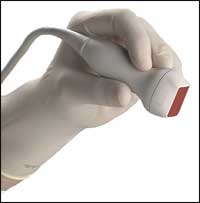
In her April 2000 testimony before the Occupational Safety and Health Administration (OSHA of Washington DC), Joan P. Baker, MSR, RDMS, RDCS, FSDMS, director of global marketing for Sound Ergonomics (Kirkland, Wash), identified the activities that tend to aggravate pain: applying pressure, abducting the shoulders, twisting the neck/trunk (sustained and repetitive), performing studies at the patient’s bedside, and holding the transducer.
 |
| University of Wisconsin?s Phyllis King notes that budget impacts both product-purchasing decisions and administrative protocols. |
Design Fixes
The incidence rate of some of these problems can be reduced through ergonomic product design. “Each new generation of ultrasound equipment is more ergonomic,” says Josh Westmoreland, ergonomist engineer at the Duke University Occupational & Environmental Safety Office (OESO of Durham, NC).
New technology helps. Flat-screen monitors are lighter than cathode ray tube monitors, allowing them to be mounted on adjustable arms and maneuvered for easier viewing. Voice-activated keyboards, ergonomic consoles, dual-monitor setups, and lighter-weight scanners allow better positioning and reduce stress on limbs and joints.
Standards also help. In 2003, the Society of Diagnostic Medical Sonography (SDMS of Plano, Tex) published industry standards, which were created during a consensus conference and are for the prevention of work-related musculoskeletal disorders. Baker, who chaired the project, notes that manufacturers were involved in the creation of these standards and are able to select those that they want to incorporate into their designs.
“Manufacturers have made some good changes. Transducer sizes, shapes, textures, and weights have changed. Cords are lighter and more flexible. Images are captured more quickly, reducing the time and force needed for an exam,” says Phyllis King, PhD, OTR, FAOTA, professor and chair of the department of occupational therapy in the College of Health Sciences at the University of Wisconsin—Milwaukee.
But even so, it isn’t enough, points out King, who notes that the percentage of sonographers complaining of pain has not decreased.
It’s in the Accessories
When the product cannot be modified, it can be accessorized. “Until a year and a half ago, sonographers and [expectant] mothers watched the same monitor during fetal ultrasound exams at our fetal diagnostic center. Often, this meant an uncomfortable or awkward scanning position for the sonographer,” Westmoreland says. “But the center brought in a second viewing monitor for the [expectant] mother and mounted it on the wall, so now both can see the image comfortably.”
Patient beds or tables are another accessory worth the investment. “Newer beds feature height adjustment with motor controls and cutout features that allow closer patient access,” Westmoreland notes.
The proper chair also is important. “Most chairs do not go high enough to keep the arm less than 30? abducted, so sonographers need a special chair to raise them high enough to reduce the abduction angle and keep their bodies in good postural alignment,” Baker explains. A saddle chair, which allows the user to sit facing forward or backward, is ideal. And it should remain stable—not roll across the room as the sonographer applies pressure to the patient.
“The biggest impact is going to come from ergonomic beds and chairs,” Westmoreland says. “But for their price, bolsters offer great value.” Resting the arm during scanning can reduce pressure on the neck and shoulders. Bolsters, which come in a variety of shapes and sizes, can provide that support.
If bolsters aren’t available, a pile of sheets or support cushions will do. “But avoid pillows—they are too soft,” Baker says, suggesting that a cable brace also can be effective. “It traps the cable just below the elbow and takes the torque off the wrist.”
Ergonomic Economics
Sheets and bolsters are a great value and, therefore, are easy to justify. However, more expensive items also will provide a return on investment. “These costs are very incidental compared to the cost of occupational injury to the sonographer,” Baker says.
Adds Chattanooga State’s Hancock, “In a profession with [accredited] laboratories that already are nearly 50% short-staffed, with another potential 25% of our profession anticipated to retire or leave the field within a handful of years, health care organizations simply cannot afford to lose their presently trained and certified sonographers to careless, ergonomically related incidences. That cost, in and of itself, is going to continue to be much too great to afford.”
If the midrange value of sonographer-generated revenue is $400,000 per year, or $33,000 per month, then having a sonographer absent because of injury will include the loss of this revenue as well as expenses related to medical costs and workers’ compensation.2 Baker’s research shows that medical bills for the average shoulder injury, not including surgery, are $20,000; and workers’ compensation is $29,000 to $32,000 per year per injured employee.2
“These costs do not include the need to hire and train temporary replacements or deal with administrative issues,” Baker notes. Comparatively, the hospital can buy support cushions for $250, height-adjustable stools for $755, ergonomic exam tables for $7,400, and ergonomic ultrasound scanners for $120,000 to $180,000, according to Baker.2
 |
| Duke University?s Josh Westmoreland expects ergonomic beds and chairs to have the greatest impact on reducing injury, but suggests bolsters, which provide great value for the price. |
Administrative Fixes
Budget also will play a role in whether protocol is adjusted to reflect ergonomic concerns. “Budget not only affects what type and how many pieces of equipment are available, but it also impacts scheduling, staffing, and productivity,” King says, citing guidelines that recommend limiting scan time per hour. The SDMS industry standards, for example, suggest limiting transducer time per hour, though more research is needed to determine the exact amount of recommended time.1
Adjustments also can be introduced during training. “Building prevention into the curriculum is an effective approach to reducing musculoskeletal disorders in sonographers,” King says.
Unfortunately, it isn’t always possible for these administrative or product fixes to be made. Budget does play a factor, and changes usually are implemented slowly. But sonographers can take matters into their own hands. Providing input on ergonomic equipment, actually using it, and staying aware of body mechanics can help to reduce the risk of injury. (For more strategies, see “Self Help for Sonographers to Avoid Work-Related Injuries“.)
“Sonographers need to educate themselves about the risk factors. No one else is in the position to look out for them, so they must do it,” says Baker, whose advice can help sonographers avoid becoming a statistic.
Renee DiIulio is a contributing writer for Medical Imaging.
References
1. Society of Diagnostic Medical Sonography. Industry standards for the prevention of work-related musculoskeletal disorders in sonography. Available at: SDMS. Accessed May 4, 2006.
2. Baker JP. Economics of Ergonomics. Sonoworld: The Ergonomics Center. Available at: SonoWorld. Accessed March 6, 2006.
Rich Smith is a contributing writer for Medical Imaging.