Radiation therapy has been established as an effective local therapy. During the past few decades, one trend in radiation therapy has been smaller fields being treated to higher doses. This trend has been facilitated by improvements in target definition and delivery. CT was the first innovation in target definition in that radiation oncologists were able to see the soft-tissue anatomy that they were irradiating. The development of 3D treatment planning in the 1980s led to the improvements in sparing normal structures. More recently, intensity-modulated radiation therapy (IMRT) has permitted radiation oncologists to sculpt a 3D dose cloud around the target volume. Current developments in stereotactic body radiation therapy (SBRT) extend this principle even further.
The latest weapon in the radiation oncologist’s arsenal for treating cancer is image-guided radiation therapy (IGRT). Historically, all radiation treatments are image guided, but IGRT is understood to incorporate recent innovations in both target delineation and in-room corrections.
Target delineation plays a major role in the treatment-planning process. In addition to CT, MRI provides improved soft-tissue definition. PET/CT and MR spectroscopy now provide functional images that will allow the active tumor to be imaged and treated rather than the shadows cast by radio-opacity. Novel applications of new technologies, such as cine-MRI and 4D CT, provide unprecedented temporal and spatial information about the tumor and surrounding structures. These technologies permit the radiation oncologist to better define the target structures and margins with much greater certainty.
Scientists and clinicians in a variety of studies have used these technologies to determine that our previous approaches to treatment using bony landmarks for aligning patients are inadequate for the higher doses and smaller margins that we now use. For instance, even if we align the bony anatomy perfectly, the organs themselves will move relative to the bones. In-room IGRT technologies permit 3D images of the patient to be imaged immediately prior to treatment. Additionally, other forms of imaging and tracking technology allow us to monitor the patient during treatment. This review will discuss the technology of the in-room IGRT systems currently available.
History of Development
Prior to the CT era, bony anatomy were used to define volume to be irradiated. Thus, images taken using the treatment beam through the treatment port—portal images—were used to establish proper patient-beam alignment. As early as the era of Cobalt-60, image quality was poor owing to low contrast, resulting from the higher beam energy and poor resolution due to the large source size (~1 cm). As linear accelerators developed, source size became much smaller (~2 mm) and images became sharper but still lacked contrast. Scientists attempted to use x-ray tubes attached to the side or incorporated into the head of both Cobalt-60 units and linear accelerators. However, these early systems had problems with either stability or the lack of coincidence of the imaging and treatment sources locations.
In the late 1980s and early 1990s, scientists and industry developed a variety of different electronic portal imaging devices. Although the initial goal of this development was to provide improved image quality, the primary advantage turned out to be convenience. Specifically, the ability to take images with the patient on the table and to review them instantaneously, rather than waiting for the film to be processed, permitted adjustments to be made prior to treatment. The latter helped motivate vendors into developing remotely adjustable couches.
Scientists and clinicians also came to understand that the target structure and surrounding tissues were moving relative to the bony anatomy, so alignment with bony anatomy was insufficient if radiation doses that correlate with tumor control were to be increased. Prostate was the focus of many of these studies as IMRT facilitated dose escalation. A variety of different approaches including rectal balloons, transabdominal ultrasound, and implanted radio-opaque seeds, were developed.
Scientists and industry began to develop different approaches to image patients in real time. These devices and associated techniques and software are now coming into routine use at many centers. We will describe only selected commercially available image-guidance technologies.
CT on Rails
Varian Medical Systems (Palo Alto, Calif), in cooperation with GE Healthcare (Waukesha, Wis), as well as Siemens Medical Solutions (Malvern, Pa) produce a system with a CT and linear accelerator. The CT and accelerator share the same carbon fiber couch. The patient is set up using external marks (such as tattoos and lasers), and then the couch swings around and is translated to a position in space. The CT is mounted on a set of rails and moves around the couch to produce a CT image. Sensors that detect collisions are incorporated into the system to ensure patient safety. Image quality is excellent, since the CT on rails is a diagnostic CT. Despite the good image quality, however, robust registration algorithms still need to be developed. This type of system has been applied to both motion studies of the prostate and SBRT, and it has the potential to be applied to adaptive radiation therapy. Reports indicate that generating a scan adds approximately 5 to 10 minutes to a patient treatment. For those contemplating such a system, retrofit of an existing linear accelerator could be difficult because there might not be sufficient room in the existing vault. Prospective design is certainly easier.
Kilovoltage Cone Beam CT
 |
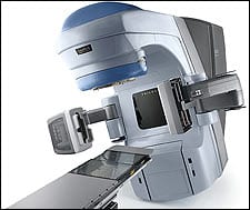
| Figure 1. Varian Trilogy with On-Board Imager features retractable arms with which to image the patient using a cone beam of kV energy. |
A CT scanner may be considered as a single plane of detectors that captures a collimated fan beam of radiation to image a single slice of the patient. The patient is translated through the fan beam, and the volumetric images are reconstructed slice by slice. Current CT detectors may have multiple sets of fan beams and detectors; however, the principle is the same.
In contrast, with cone beam CT (CBCT), a flat-panel detector is used to capture a diverging cone beam of x-rays to generate a volumetric image. The flat-panel detector is mounted on the gantry of the treatment machine, and the gantry is rotated to create the CT scan. CBCT is a new technology that has developed in part as a result of innovative image processing and improvements in flat-panel imaging. The major advantage of CBCT is that the patient is imaged in the setup position on the treatment couch with a turn of the gantry.
 |
| Figure 2. The Synergy system from Elekta Inc (Norcross, Ga) also features a kV imaging system deployed with retractable arms to image the patient in the treatment position. |
Major accelerator vendors have starting marketing systems with retractable arms placed orthogonal to the treatment system. Examples are shown in Figures 1 and 2. These systems use similar detector systems, but instead of using the treatment beam to create an image, an x-ray tube (up to ~120 kVp) is used to create the image.
In contrast to megavoltage x-ray imaging, image quality is improved by the higher contrast from diagnostic x-rays and more efficient x-ray detection. However, compared to diagnostic CT, the images tend to be poorer quality—scattered radiation from the cone beam is larger than from a fan beam because there is a greater volume irradiated, resulting in a reduction in the signal-to-noise ratio and, hence, image quality. Also, there are limitations in the length of the image that can be captured with a single turn of the gantry.
Typical images produced by this method, shown in Figure 3, are expected to improve as innovations are developed by both scientists and industry. However, current images are sufficient to detect 3D bony landmarks and soft-tissue contrast. Although artifacts are still present, resulting from scattered radiation and motion, motion artifacts are worse with CBCT since the acquisition time is ~1 minute compared to ~1 second in a diagnostic x-ray unit. Because scatter reduces image quality, larger objects with larger cone angles (such as the pelvis) will produce poorer images than targets of smaller anatomy (such as the skull).
 |
| Figure 3. To treat a lung lesion laying on the posterior chest wall, CBCT images are compared to the planning CTs to align the lesion for accurate treatment. The cross-hairs (green and red lines) denote the center of the high dose volume (iso-center). The CBCT image (brighter image displayed) is fused onto the reference (treatment planning) CT (the darker image displayed). Notice that the alignment is to the lesion (target) and not to the patient skin contours. |
In addition to providing CBCT, the imaging system is capable of providing orthogonal fluoroscopic and radiographic images, which are used for patient setup. Typically, this alignment does add several minutes to the patient-setup process. The diagnostic quality of these images compared to portal images makes alignment, in many cases, easier and presumably more accurate. Currently, vendors are providing overlays of planned with acquired images for patient alignment. Robust registration algorithms for comparing CBCT images and planned CT volume sets are being developed.
 |
| In an enlarged view of the target volume, the gray-scale picture is the CBCT matched with the reference CT. The color lines are the target volume that was specified by the physician. Images provided by Varian Medical and produced on the company?s On-Board imager attached to the Clinac machine, not Trilogy. |
Megavoltage Cone Beam CT
Electronic portal imaging devices (EPIDs) use a metal plate bonded to a phosphor screen as the primary radiation detector. Treatment x-rays cause the phosphor to glow, and the resulting light is detected by an array of photodiodes generated with a technology similar to that used for producing flat-panel displays. These EPIDs are in widespread use. The new application of these systems is to produce a volumetric CT image by rotating the gantry around the patient with the patient in the treatment position on the couch.
Unlike kV CBCT, MV CBCT requires only the electronic portal imager, which is more common than the robotic arms. MV CBCT offers the capability, therefore, to acquire 3D image sets for a lower cost. However, megavoltage CT suffers from the same limitations that megavoltage portal images do. Specifically, due to the nature of the x-ray interactions at megavoltage energies, the contrast is low. Moreover, the fraction of x-rays detected by the flat-panel imager is small (~2%) due to the high energy of the x-rays. However, it does have some advantages over kV CBCT. The scatter to primary ratio is ~30% compared to the ~200% in kV CBCT. Patient doses tend to be a concern, being approximately ~10 cGy per image. The use of such a high dose, however, is not negligible compared to the prescribed dose. Some clinics have suggested incorporating this radiation dose into the clinical plan.
Image quality is sufficient to detect bone contrast, and as such these systems can be used to improve setup error. One advantage of MV CBCT is that streaking artifacts are minimized since high Z materials, such as bone, do not absorb the x-rays as strongly. It is expected that further refinements to this approach may lower patient dose and improve image quality.
Tomotherapy
 |
| Figure 5. With helical tomotherapy from Tomotherapy, an x-band accelerator is mounted in an 85-cm bore gantry of a helical CT. |
Serial tomotherapy—as developed in the early 1990s by NOMOS Corp (Cranberry Township, Pa), now a North American Scientific company, using the MIMiC system—was a pioneer in IMRT. No specific imaging developments were used in conjunction with serial IMRT. Helical tomotherapy was started with image guidance in mind, and the first paper on helical tomotherapy was published in 1993. The concept behind tomotherapy is illustrated in Figure 5. An x-band accelerator is mounted in an 85-cm bore gantry of a helical CT scanner. The patient is progressively translated through the CT, and high quantum efficiency detectors (~10x higher than for MV cone beam CT) are used to acquire the x-ray image information. These detectors have two advantages over the flat-panel technologies used in CBCT. First, high efficiency means that the x-ray dose resulting from imaging is used efficiently, resulting in high-quality images. Second, the high efficiency and narrow fan beam provide less scatter to the detectors, making exit dosimetry a possibility. Exit dosimetry attempts to compute the actual dose delivered to the patient based upon the radiation that is transmitted through the patient, but it is still under development by TomoTherapy Inc (Madison, Wis) and is not available on the commercial product.
Tomotherapy is designed to deliver IMRT treatments using a binary multi-leaf collimator (MLC) with a leaf transmission < 1%. There are 64 leaves, with nominal 6.25 mm at isocenter, resulting in a 40-cm field. The system generates intensity modulation in a pixilated fashion, like step and shoot or segmented IMRT. Each pixel intensity is determined by the length of time the pixel is blocked by the binary MLC.
Since the radiation is along a helix, tomotherapy has the ability to deliver along every possible gantry angle; hence, it provides an inherently higher degree of freedom than IMRT. In principle, this advantage should yield improved dose distributions compared to linac-based IMRT. However, because of the design, tomotherapy cannot treat noncoplanar geometries, which may affect such sites as the brain, where fields from above the head are often used. The trade-off between these two effects is expected to be site- and potentially patient-specific.
The imaging field of view also is 40 cm, but the treatment field can be larger (up to 60 cm), although at the sacrifice of uniformity. For imaging, the energy is degraded to 3.5 MV and the output is lowered, resulting in a typical imaging dose that is 0.5 to 3 cGy, which is acceptable for portal imaging. Future developments in tomotherapy include automated correction for patient positioning using sophisticated software that employs mutual information for registration and deformation algorithms.
Other Technologies
One very promising technology is the use of active markers. Calypso Medical Technologies Inc (Seattle) has developed an electromagnetic tracking system that is complementary to existing technologies. The system consists of a radio-translucent array that hangs off the end of a cart in the room. Small implanted markers called beacons interact with the electromagnetic field generated by the array, and software calculates the location of each beacon in real time with submillimeter precision. Although the system does not generate an image, it facilitates real-time monitoring during treatment, something that none of the systems discussed currently offer. Thus, an IGRT system could be used to establish the volumetric location of the organs, and Calypso beacons could monitor its motion during treatment.
Conclusions
IGRT is developing rapidly both technologically and clinically. Development of a robust registration algorithm for comparing the setup information to the planned data is anticipated shortly. Even without this software, the initial clinical results have shattered some illusions about how we were treating patients with radiation therapy. As we peer inside the patient prior to, during, and immediately after each treatment, and we see and measure the variations in target position, we may realize that margins are inappropriate, positioning needs to change, and the dose that we thought we were delivering to the tumor and critical structures is not exactly what we had planned. IGRT will act as a quality-assurance tool, and as we learn more from this technology, we can design potentially better patient-specific treatment plans. This may lead to reduced toxicity, facilitate dose escalation, and ultimately improve the cure. MI
Dennis Mah, PhD, is associate professor at Albert Einstein College of Medicine (Bronx, NY), and deputy director of physics in the department of radiation oncology at Montefiore Medical Center (New York).


